Liquid Glass: The iOS Effect, Explained
How Apple achieves its stunning Liquid Glass effect — broken down mathematically and rebuilt, one shader pass at a time.
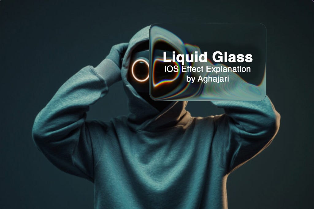
Hello everyone! In this article, we'll explore how Apple achieves its stunning Liquid Glass effect, break down the visual behavior mathematically, and recreate it using Shaders. The implementation is platform-agnostic and can run anywhere.
- 01 Background Sample the source image, untouched.
- 02 SDF panel A signed distance field masks the rounded rectangle.
- 03 Lens distortion A circular profile bends sample coordinates outward.
- 04 Chromatic aberration RGB channels split near the steep edges.
- 05 Gaussian blur A soft, distance-aware blur adds depth.
01 — Foundations
Why Shaders Are the Perfect Tool for Liquid Glass
At first glance, the Liquid Glass effect looks like a simple background blur with a little distortion, something we've all seen before. Normally, you could get away with blurring the background once, caching the result as a bitmap, and then just offsetting that pre-blurred image behind a rounded rectangle. A single CPU pass would be enough, and performance would be fine.
But Liquid Glass is different.
The way the background warps and flows depends entirely on the exact position, size, and corner radius of the foreground "glass" panel at any given moment. As your finger drags the panel across the screen, the distortion field has to update in real time — every single frame. If you tried to do this the traditional way (grabbing the background, processing it on the CPU, manipulating pixels in a bitmap), you'd be redrawing and re-blurring massive portions of the image 60 times per second. That's brutally expensive and would crush frame rate almost instantly.
This is where shaders save the day.
By moving the entire effect to the GPU with a fragment shader, we can compute the exact distortion and blur for every pixel on the fly, using the panel's current position as a uniform. The GPU is built for this kind of parallel, per-pixel work — it chews through millions of fragments effortlessly even on modest hardware.
02 — Setup
Setting Up Our Playground: glsl.app
To follow along and experiment in real time, we'll use the online GLSL editor: https://glsl.app/. It lets you write, run, and instantly see shader code with live uniforms.
Quick setup:
- Open https://glsl.app/
- Click the Textures tab at the top
- Drag any image into the Texture 0 slot — this will be our background
I'm using the free augmented-reality-themed stock photo throughout the article.
Once loaded, the editor gives us a bunch of built-in uniforms we'll be using:
in vec2 uv;                        // Normalized coordinates: (0,0) = bottom-left, (1,1) = top-right
out vec4 out_color;                // Final color of the current fragment (our job!)
uniform vec2 u_resolution;         // Canvas size in pixels
uniform float u_time;              // Time in seconds (great for animations)
uniform vec4 u_mouse;              // Mouse position + click state (x, y, left-click, right-click)
uniform sampler2D u_textures[16];  // Array of textures – we'll use index 0 for our background
Why these matter for Liquid Glass:
- uv
- lets us sample the background texture with proper aspect ratio
- u_mouse
- we'll treat the current mouse position as the center of our floating glass panel
- u_resolution
- needed to convert between pixel and normalized spaces when calculating distances and offsets
03 — Step 1
Displaying the Background Texture
Let's start with the basics, just rendering our background image correctly across the entire canvas.
Here's the initial shader:
#version 300 es
precision highp float;
precision highp sampler2D;

in vec2 uv;
out vec4 out_color;
uniform vec2 u_resolution;
uniform vec4 u_mouse;
uniform sampler2D u_textures[16];

vec3 getTextureColorAt(vec2 coord) {
    return texture(u_textures[0], coord / u_resolution.xy).rgb;
}

void main() {
    vec2 fragCoord = uv * u_resolution;
    vec3 backgroundColor = getTextureColorAt(fragCoord);
    out_color = vec4(backgroundColor, 1.0);
}
What's happening here?
- uv comes in normalized coordinates.
- We multiply by u_resolution to work in pixel space when needed.
- getTextureColorAt() is a small helper that takes pixel coordinates, converts them back to UV space, and samples Texture 0 (our background image).
- Right now, we're just passing the original pixel color straight through, no blur, no distortion, no magic yet.
04 — Step 2
Drawing the Rounded Glass Panel
Now let's create the actual glass panel, a draggable rounded rectangle that follows the mouse.
The trick in fragment shaders is that we don't draw shapes the traditional way. Instead, every pixel decides for itself: "Am I inside the glass or outside?" We do this using a Signed Distance Field (SDF).
The SDF Function
float sdf(vec2 p, vec2 b, float r) {
    vec2 d = abs(p) - b + vec2(r);
    return min(max(d.x, d.y), 0.0) + length(max(d, 0.0)) - r;
}
Think of a normal rectangle first. If you subtract the rectangle's half-width and half-height from the pixel's position and take the absolute values, you know how far you are from the center edges. Here p is that pixel's position and b is the half size of glass.
Now imagine you want rounded corners r: we simply pretend the corners are pushed inward by the corner radius. The math inside the function checks two things at once:
- In the middle of the sides: it measures the straight-line distance to the nearest flat edge.
- In the corner areas: it measures the distance to the invisible quarter-circle that forms the round corner.
After a tiny bit of vector wizardry, the function returns:
a negative number if the pixel is inside the shape,
zero exactly on the border,
a positive number if the pixel is outside.
That single number is pure gold in shaders: it lets us draw perfectly smooth rounded rectangles and know exactly which pixels belong to the glass panel.
Using the SDF to mask our glass
Here's the full shader with the glass overlay:
#version 300 es
precision highp float;
precision highp sampler2D;

in vec2 uv;
out vec4 out_color;

uniform vec2 u_resolution;
uniform vec4 u_mouse;
uniform sampler2D u_textures[16];

vec3 getTextureColorAt(vec2 coord) {
    return texture(u_textures[0], coord / u_resolution.xy).rgb;
}

float sdf(vec2 p, vec2 b, float r) {
    vec2 d = abs(p) - b + vec2(r);
    return min(max(d.x, d.y), 0.0) + length(max(d, 0.0)) - r;
}

void main() {
    vec2 fragCoord = uv * u_resolution;
    vec3 backgroundColor = getTextureColorAt(fragCoord);

    vec2 glassSize = vec2(120.0, 80.0);
    vec2 glassCenter = u_mouse.xy;
    vec2 glassCoord = fragCoord - glassCenter;

    float size = min(glassSize.x, glassSize.y);
    float inversedSDF = -sdf(glassCoord, glassSize * 0.5, 16.0) / size;

    if (inversedSDF < 0.0) {
        // Outside the glass → show untouched background
        out_color = vec4(backgroundColor, 1.0);
        return;
    }

    // Inside the glass → darken slightly to simulate tinted glass
    vec3 glassColor = backgroundColor * 0.50;

    out_color = vec4(glassColor, 1.0);
}What's happening here?
First, it turns the normalized uv coordinate (which goes from 0 to 1 across the canvas) into real pixel coordinates by multiplying with u_resolution. This gives us fragCoord, the exact x, y position of the current pixel in pixels. It then samples the background image at that spot and stores the color as backgroundColor. So far, nothing special, we just have the original picture.
Next, it decides where the glass panel lives: its center is simply wherever your mouse (or finger) currently is (u_mouse.xy). The size of glass is defined in glassSize(we pass half of that to the SDF later), and the corners are rounded with a 16-pixel radius.
For every pixel, the shader subtracts the glass center from the pixel's position. This shifts everything into glass local space, where the center of the rounded rectangle is at (0,0). That shifted position (glassCoord) is handed to the SDF function along with the half-size (glassSize * 0.5) and corner radius.
The SDF instantly returns a negative number if the pixel lies inside the rounded rectangle and a positive number if it lies outside — zero means exactly on the edge. We flip the sign with -sdf(…) and divide by the smaller side length just to normalize and keep the numbers tidy. The result (inversedSDF) is now negative when we're outside the glass and positive (or zero) when we're inside.
Finally, the shader checks that value:
- If inversedSDF < 0.0 → we're outside → output the untouched background color and finish.
- Otherwise → we're inside the glass → take the same background color, multiply it by 0.50 to darken it (simulating a light tint), and output that instead.
05 — Step 3
Applying the Liquid Glass Effect
Now that we can identify which pixels lie inside our glass panel, it's time to implement the core algorithm that transforms ordinary pixels into the mesmerizing liquid glass effect.
Since we're now working exclusively with pixels inside the rounded rectangle, our inversedSDF values have shifted to a range of [0, 0.5] , where:
- 0.5 represents the very center of the glass panel
- 0 represents pixels exactly on the edges
The secret to liquid glass lies in creating a lens effect, simulating how light bends when passing through curved glass. Real glass doesn't just tint the background; it warps and magnifies what lies beneath it.
The Mathematics of Glass Distortion
Here's the core algorithm:
float distFromCenter = 1.0 - clamp(inversedSDF / 0.3, 0.0, 1.0);
float distortion = 1.0 - sqrt(1.0 - pow(distFromCenter, 2.0));
vec2 normalizedGlassCoord = normalize(glassCoord);
vec2 offset = distortion * normalizedGlassCoord * glassSize * 0.5;
vec2 glassColorCoord = fragCoord - offset;

vec3 glassColor = getTextureColorAt(glassColorCoord);
glassColor *= vec3(0.90); // Glass tint
Let's break this down step by step:
Step 3.1: Remapping Distance from Center
float distFromCenter = 1.0 - clamp(inversedSDF / 0.3, 0.0, 1.0);We're transforming our inversedSDF values into a more useful representation of distance from the glass center:
- Division by 0.3: This effectively "zooms in" on the central 60% of our glass panel. By dividing inversedSDF by 0.3 instead of 0.5, we're saying that pixels beyond 0.3 units from the edge should be treated as if they're at maximum distance from center.
- Clamp to [0,1]: This ensures our values stay within a predictable range, preventing any overflow.
- Inversion: We flip the values so that:
- Center pixels (e.g inversedSDF = 0.5) become distFromCenter = 0.0
- Edge pixels (e.g inversedSDF = 0.0) become distFromCenter = 1.0
Step 3.2: Creating the Lens Distortion Curve
float distortion = 1.0 - sqrt(1.0 - pow(distFromCenter, 2.0));This equation implements a circular lens profile that mimics how real glass bends light. Squares our distance value, creating a quadratic curve and then takes the square root, which mathematically describes a quarter-circle (x²+y²=1 → y²=1-x² → y = sqrt(1-x²)).
The result? A smooth curve where:
- Edge pixels (distFromCenter = 1.0) get maximum distortion (distortion ≈ 1.0)
- Center pixels (distFromCenter = 0.0) get zero distortion (distortion = 0.0)
- Between center and edge : A smooth, curved transition that feels natural and organic
y = 1.0 − sqrt(1.0 − x²)
The faint line is the x² / 2 approximation — close near the center, diverging toward the edge.
This specific mathematical formula 1.0 - sqrt(1.0 - x²) is commonly used in optics to define the geometry of curved lens or mirror surfaces, which determines how light rays refract or reflect according to principles like Snell's law. In computer graphics, particularly in ray tracing and physically based rendering, this formula helps model accurate intersections and normals for simulating realistic optical effects in scenes involving lenses or curved objects. Additionally, for a simpler approximation (in scenarios where x is small), the expression can be approximated as x² / 2, which simplifies calculations while maintaining sufficient accuracy.
Step 3.3: Calculating the Pixel Offset
vec2 offset = distortion * normalizedGlassCoord * glassSize * 0.5;Now we determine how much to "shift" each pixel to create the warping effect:
- distortion is a strength factor in the range [0, 1], where 0 means no warping and 1 applies the full lens curvature effect. Edge pixels get maximum offset while center pixels won't shift at all.
- normalizedGlassCoord contains the fragment's position in glass-local space, normalized to the range [-1, 1] in both X and Y (i.e. the center of the glass is (0,0), the left/right edges are ±1 on X, and top/bottom edges are ±1 on Y).
- Multiplying by normalizedGlassCoord scales the distortion strength radially: the offset is zero at the center and grows linearly toward the edges, while preserving direction (outward from the center).
- Finally, glassSize * 0.5 (half the glass panel's width/height in pixels) converts the normalized offset [-1, 1] into actual pixel units in the range [-glassSize/2, +glassSize/2]. This ensures the calculated displacement is expressed in screen-space pixels, with (0,0) corresponding to the exact center of the glass.
The result is a smooth, radially symmetric offset that pushes pixels outward from the center proportionally to their distance, producing the classic convex magnifying-glass bulge.
Step 3.4: Sampling the Distorted Background
vec2 glassColorCoord = fragCoord - offset;

vec3 glassColor = getTextureColorAt(glassColorCoord);
glassColor *= vec3(0.90); // Glass tint
Finally, we sample the background texture at the offset position:
- fragCoord - offset: We subtract the offset (rather than add) because we want to sample from behind where the glass would magnify from.
- getTextureColorAt(glassColorCoord): Retrieves the color from our calculated position
- glassColor *= vec3(0.90): Applies a subtle 10% darkening to simulate the slight tinting effect of real glass
Output
Wait… this is literally just a magnifying lens!
To prove it, try this quick experiment:
Reverse the condition and apply the exact same distortion code to the background while leaving the inside of the glass untouched.
glassColorCoord = fragCoord - offset — the inside of the glass stays clear while the surrounding background bends like a magnifying lens.This would happen if instead we used addition in glassColorCoord (fragCoord + offset): The behavior would completely reverse, every pixel would sample inward toward the center.
glassColorCoord = fragCoord + offset — the displacement flips, so the background pulls inward toward the panel instead of bulging out.06 — Step 4
Adding Chromatic Aberration
Now let's elevate our liquid glass effect to the next level of realism by implementing Edge-Only Chromatic Aberration. It's a physically accurate simulation of how light actually behaves when passing through curved glass surfaces.
Understanding Real-World Chromatic Aberration
In real optical systems like lenses, water droplets, and curved glass, chromatic aberration occurs because different wavelengths of light bend at slightly different angles when passing through curved surfaces. This phenomenon is most pronounced at the edges where the curvature is steepest, while the center remains relatively clean and undistorted.
Edge-Only Aberration means:
- Center of glass → clean, color-accurate magnification
- Edges of glass → red/blue/green color fringing
- Gradual transition → smooth falloff between clean center and aberrated edges
Calculating the Chromatic Shift
float edge = smoothstep(0.0, 0.02, inversedSDF);
vec2 shift = normalizedGlassCoord * edge * 3.0;

vec3 glassColor = vec3(
  getTextureColorAt(glassColorCoord - shift).r,
  getTextureColorAt(glassColorCoord).g,
  getTextureColorAt(glassColorCoord + shift).b
);
This line determines how much to offset each color channel:
- edge : Controls the intensity (stronger at edges, weaker toward center)
- 3.0 : A scaling factor that controls the overall aberration strength
Instead of sampling all three color channels from the same location, we sample each channel from a slightly different position:
glassColorCoord - shift (shifted toward the glass center) glassColorCoord (our original, undistorted position) glassColorCoord + shift (shifted away from the glass center) Why these specific directions?
- Red light has longer wavelengths and bends less in real glass, so it appears to come from behind
- Green light serves as our reference (middle wavelength)
- Blue light has shorter wavelengths and bends more, so it appears to come from ahead
What You'll See Visually
With edge-only chromatic aberration implemented, your liquid glass now exhibits:
- Clean Center : The middle of the glass panel shows crisp, color-accurate magnification
- Rainbow Fringing : The edges display subtle red and blue color separation
- Smooth Transition : The aberration gradually increases from center to edge
- Physical Realism : The effect mimics how real curved glass disperses light
- Dynamic Response : As you move the glass panel, the aberration follows the edges naturally
Output
07 — Step 5
Adding Blur Effect to the Glass Panel
Now we'll complete our liquid glass effect by adding the final crucial component: background blur . Real glass doesn't just magnify and distort the background, it also creates a soft, dreamy blur that gives the material its characteristic depth and translucency.
Up until now, our shader has been creating a convincing magnifying lens with chromatic aberration, but it's been too sharp and clear. Real liquid glass has a subtle blur that varies across its surface, being clearest at the center and gradually becoming more diffused toward the edges.
Implementing Gaussian Blur
vec3 getBlurredColor(vec2 coord, float blurRadius) {
    vec3 color = vec3(0.0);
    float totalWeight = 0.0;

    for (int x = -2; x <= 2; x++) {
        for (int y = -2; y <= 2; y++) {
            vec2 offset = vec2(float(x), float(y)) * blurRadius;
            float weight = exp(-0.5 * (float(x*x + y*y)) / 2.0);

            color += getTextureColorAt(coord + offset) * weight;
            totalWeight += weight;
        }
    }

    return color / totalWeight;
}
This function implements a 5x5 Gaussian blur kernel :
- Sampling Pattern: We sample 25 pixels in a 5×5 grid around each fragment
- Gaussian Weights: Each sample is weighted using the Gaussian formula exp(-0.5 * distance²), giving more importance to closer pixels
- Variable Radius: The blurRadius parameter lets us control how spread out our samples are
- Normalization: We divide by totalWeight to ensure the final color maintains proper brightness
Calculating Dynamic Blur Intensity
float blurIntensity = 1.2;
float blurRadius = blurIntensity * (1.0 - distFromCenter * 0.5);
Here's where the magic happens:
- blurIntensity : Controls the maximum blur strength (higher = more blur)
- Distance-based variation : (1.0 - distFromCenter * 0.5) creates a gradient where:
- Center pixels (distFromCenter = 0.0) get blurRadius = blurIntensity * 1.0 (full blur)
- Edge pixels (distFromCenter = 1.0) get blurRadius = blurIntensity * 0.5 (half blur)
Output
08 — Try it yourself
The Liquid Glass Playground
Every parameter we just derived, in one place. Drag the panel around the canvas, sweep the sliders, or slide Effect amount from 0 to 1 for a clean before/after between the raw background and the full material.
09 — Source
GLSL Source Code
#version 300 es
precision highp float;
precision highp sampler2D;

in vec2 uv;
out vec4 out_color;

uniform vec2 u_resolution;
uniform vec4 u_mouse;
uniform sampler2D u_textures[16];

vec3 getTextureColorAt(vec2 coord) {
    return texture(u_textures[0], coord / u_resolution.xy).rgb;
}

float sdf(vec2 p, vec2 b, float r) {
    vec2 d = abs(p) - b + vec2(r);
    return min(max(d.x, d.y), 0.0) + length(max(d, 0.0)) - r;
}

vec3 getBlurredColor(vec2 coord, float blurRadius) {
    vec3 color = vec3(0.0);
    float totalWeight = 0.0;

    for (int x = -2; x <= 2; x++) {
        for (int y = -2; y <= 2; y++) {
            vec2 offset = vec2(float(x), float(y)) * blurRadius;
            float weight = exp(-0.5 * (float(x*x + y*y)) / 2.0);

            color += getTextureColorAt(coord + offset) * weight;
            totalWeight += weight;
        }
    }

    return color / totalWeight;
}

void main() {
    vec2 fragCoord = uv * u_resolution;
    vec2 glassSize = vec2(120.0, 80.0);
    vec2 glassCenter = u_mouse.xy;
    vec2 glassCoord = fragCoord - glassCenter;

    float size = min(glassSize.x, glassSize.y);
    float inversedSDF = -sdf(glassCoord, glassSize * 0.5, 16.0) / size;

    if (inversedSDF < 0.0) {
        out_color = vec4(getTextureColorAt(fragCoord), 1.0);
        return;
    }

    vec2 normalizedGlassCoord = normalize(glassCoord);
    float distFromCenter = 1.0 - clamp(inversedSDF / 0.3, 0.0, 1.0);
    float distortion = 1.0 - sqrt(1.0 - pow(distFromCenter, 2.0));
    vec2 offset = distortion * normalizedGlassCoord * glassSize * 0.5;
    vec2 glassColorCoord = fragCoord - offset;

    float blurIntensity = 1.2;
    float blurRadius = blurIntensity * (1.0 - distFromCenter * 0.5);

    float edge = smoothstep(0.0, 0.02, inversedSDF);
    vec2 shift = normalizedGlassCoord * edge * 3.0;
    vec3 glassColor = vec3(
      getBlurredColor(glassColorCoord - shift, blurRadius).r,
      getBlurredColor(glassColorCoord, blurRadius).g,
      getBlurredColor(glassColorCoord + shift, blurRadius).b
    );

    glassColor *= vec3(0.90);  // Glass tint
    out_color = vec4(glassColor, 1.0);
}
10 — In practice
The Implementation Concept
The idea to implement this in a real application is surprisingly straightforward, just like applying a blur filter to an image. You simply take a snapshot of the background content behind where your glass panel will appear, then apply this fragment shader to your liquid glass UI component using that background snapshot as the texture input. That's it! The shader handles all the complex distortion, magnification, and chromatic aberration calculations in real-time, transforming your static background capture into a dynamic, interactive liquid glass effect that responds to user input and panel movement. For Android 13+, you can use the native RuntimeShader, which simplifies the whole process, while older versions require handling everything with traditional OpenGL ES.
There are already more customizable and advanced libraries implementing this effect across different platforms, including native Android, Compose Multiplatform, and WebGL implementations, each offering production-ready solutions with extensive configuration options and optimizations. Since these mature libraries already exist and provide comprehensive tooling for developers who need ready-to-use implementations, I'm not publishing this as a separate library.
Summary
This article provides a foundational explanation of how Apple's Liquid Glass effect works by breaking it down into five core components: using GPU shaders for real-time performance, creating rounded glass panels with Signed Distance Fields (SDF), implementing lens distortion through mathematical curves that simulate light refraction, adding edge-only chromatic aberration for physical realism, and adding blur effect. It's important to note that this is just a simple explanation of the fundamental principles. The real magic lies in how you can customize and extend these basics: you can add multiple glass layers, environmental reflections, caustic light patterns, surface ripples, depth-based distortion, animated refractions, and countless other enhancements to create increasingly realistic and sophisticated glass effects.
Publications
Moving Dots: Animating Points in OpenGL ES
From a single static point to motion — the next step in the OpenGL ES journey.
Read preview
Shading the Canvas: Vertex & Fragment Shaders
The two tiny programs that decide where things go and what color they are.
Read preview
OpenGL ES on Android: The Journey Begins
The opening chapter of a hands-on series on graphics programming for Android.
Read preview